

Mechanical Load Distribution on Industrial Metal Roof Solar Mounting Profiles
In industrial and commercial (C&I) rooftop solar installations, transferring dynamic wind suction and dead loads to trapezoidal profile sheets without exceeding local yield strengths requires rigorous mechanical profiling. Without precise point-to-line load conversion and optimal rail span matching, concentrated fastener stresses can induce purlin deflection exceeding L/250 limits and cause waterproofing failure at penetration points.

Trapezoidal Roof Point Load to Line Load Conversion
Trapezoidal metal roofs-commonly engineered with 0.5mm to 0.8mm high-tensile steel face sheets-cannot sustain arbitrary point loads induced by L-feet or mini-rails without structural deformation. The direct downward gravitational force of solar modules and ballasted or attached racking must be converted from isolated point loads into distributed line loads along the upper rib crests.
When designing for trapezoidal profiles, the concentrated clamp reaction force (P) acting on the crest must be transferred through an extruded aluminum profile (AL6005-T5) that spans across multiple ribs, effectively widening the load-bearing footprint.

The localized bending moment (M) developed in the thin steel sheet under a point load is calculated using plate bending equations, where the maximum stress must remain well below the steel's yield strength (δ_y 240MPa for standard Q255/G550 substrates).
| Parameter | Engineering Specification | Standard / Compliance |
| Roof Sheet Thickness | 0.5mm - 0.8mm (High-tensile steel) | ASTM A792 / AS 1397 |
| Rail Material | AL6005-T5 Extruded Aluminum | GB/T 6892-2006 |
| Yield Strength (δ_y) | ≥ 240MPa (Aluminum Rails) | EN 755-2 |
| Ultimate Tensile Strength | ≥ 260 MPa | ISO 6361-2 |
| Anodized Film Thickness | ≥ 10um (Class 10) | ISO 7599 |
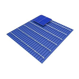
Rail Span and Roof Purlin Spacing Mechanical Matching
Optimizing the distance between roof attachment points depends directly on the structural spacing of the underlying structural steel purlins. Mismatching the solar mounting rail span with the purlin grid introduces high resonant vibration frequencies and excessive mid-span deflection under AS/NZS 1170.2 wind uplift conditions.
To prevent structural failure, the maximum allowable rail span (L_max) is governed by the section modulus (W_x) of the profile and the localized wind pressure design criteria:

where w represents the combined uniformly distributed line load (kN/m) including dead load and wind uplift.
- Purlin Alignment: Rails must be anchored directly above or adjacent to purlin supports where vertical reaction capacity is maximized.
- Cantilever Limits: Rail overhangs at terminal ends must not exceed 33% of the adjacent internal span to avoid resonant harmonic failure modes during extreme wind events (V_ult ≥60m/s).
- Thermal Expansion Joints: Continuous rail runs exceeding 30meters require thermal expansion gaps to counteract longitudinal stress accumulation caused by extreme diurnal temperature variations (△T = 50°C).

Deflection Mitigation via EPDM Gasket and Flashing Engineering
Waterproofing integrity on industrial metal roofs relies heavily on the mechanical interface between the fastener, the flashing plate, and the metal skin. Compression set resistance of the sealing element determines the long-term impermeability of the roof penetration.
When structural loads cycle between positive downward snow loads (1.4 kN/m^2) and negative wind suction, traditional rubber washers degrade and lose elasticity. Bristar utilizes high-grade EPDM (Ethylene Propylene Diene Monomer) gaskets compressed to a controlled torque specification (9-12Nm) using SUS304 structural fasteners.
- UV Resistance: EPDM formulations rated for operating temperatures between -40^C and +120^C, preventing polymer embrittlement.
- Load Spread Clamping Plates: Wide-base aluminum flashing plates distribute clamping force across a surface area of ≥ 45cm^2, reducing localized indentation of the trapezoidal crown.
- Galvanic Isolation: Non-conductive isolation pads prevent bimetallic corrosion between stainless steel fasteners and aluminum components mounted on galvanized steel sheets.
Frequently Asked Questions
How do Bristar mounting profiles handle extreme wind uplift forces up to 60m/s?
Bristar rails undergo rigorous finite element analysis (FEA) and wind tunnel testing in accordance with AS/NZS 1170.2 and Eurocode 9 standards. By optimizing wall thicknesses, hollow-chamber geometries, and high-tensile AL6005-T5 alloy properties, the system securely withstands high-velocity suction pressures without permanent plastic deformation.
What is the maximum allowable rail span for trapezoidal steel roofs?
Maximum rail spans typically range from 1,200mm to 1,800mm, depending on local wind region classifications, building height, and roof pitch. Exact engineering calculations are provided per project through our automated structural design software.
What is the standard minimum order quantity (MOQ) for custom-length solar rails?
Standard mill finishes and stock lengths (4,200mm or 5,200mm) have a flexible MOQ starting at 1,000meters. Custom anodized lengths and specialized extrusion profiles require a minimum order of 3,000meters to optimize production efficiency and shipping container utilization.