

Long-span PV arrays experience high thermal expansion stresses and wind-induced shear forces at rail junctions. Deploying internal aluminum rail splice connectors engineered from AL6005-T5 alloy with integrated bonding pins maintains structural continuity across spans over 12 meters while preventing structural buckling under thermal variation (-20°C to +70°C). Selecting the right solar rail splice kit ensures compliance with AS/NZS 1170.2 wind loading standards and maintains grounding continuity without additional jumper wires.
Structural Challenges in Long-Span Solar Racking
When solar mounting rail length exceeds 6 to 12 meters, ambient temperature fluctuations induce axial thermal expansion and contraction. For structural aluminum profiles (AL6005-T5), the linear thermal expansion coefficient is approximately $23 \times 10^{-6} \text{ K}^{-1}$. Unmitigated expansion across a continuous 30-meter rail run produces up to 34.5 mm of axial displacement over a 50°C thermal delta, generating bending moments and high localized shear stress at fixing points, solar roof hooks, and module frames.
Without dedicated expansion joints and precision-fit internal connectors, long-span arrays suffer from:
Prying action on fasteners: Shear loads loosen M8/M10 stainless steel (SUS304) mounting hardware, weakening attachment points to structural purlins.
Module frame micro-cracking: Constrained thermal movement transfers stress into module frames and glass, risking laminate delamination and micro-cracks in PV cells.
Bonding path disruption: Mechanical loosening at junction points increases electrical resistance, violating ground bonding standards like UL 2703 and IEC 61215.


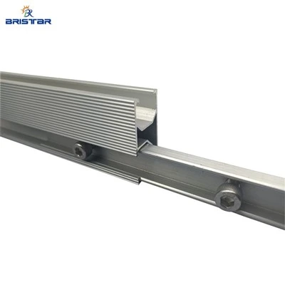
Mechanical Performance & Material Specifications: Splice Kit Engineering
Connecting structural rails across long spans requires internal or external joining profiles capable of transferring bending moments equal to or exceeding the rail's nominal moment capacity ($M_x$). Precision-extruded internal solar rail splice connectors fit into the interior channels of aluminum rails, providing structural alignment without interfering with module mid-clamps or end-clamps along the top mounting plane.
| Parameter | Specification / Standard | Value / Requirement | Impact on System Performance |
| Material Grade | ASTM B221 / EN AW-6005A-T5 | Yield Strength $\ge 240 \text{ MPa}$, Tensile $\ge 260 \text{ MPa}$ | Prevents elastic deformation under extreme wind loads |
| Fastener Material | Stainless Steel SUS304 / A2-70 | Ultimate Tensile Strength≥700 MPa | Resists atmospheric corrosion and galvanic action |
| Anodization Thickness | ISO 7599 / QUALANOD | ≥10 (Class 10) | Prevents oxidation in coastal and industrial areas |
| Max Design Wind Load | AS/NZS 1170.2 / EN 1991-1-4 | Up to 60 m/s (3second pulse) | Ensures structural survivability in Typhoon zones |
| Grounding Mechanism | UL 2703 / Stainless Steel Pins | Resistance < 0.1Ω across junction | Eliminates copper bonding jumper wires |
To achieve maximum mechanical stability, continuous solar rail junction connections must undergo static bending tests to calculate maximum bending moment resistance (Mrd$) and shear capacity (V_rd). Utilizing AL6005-T5 structural aluminum ensures that the splice profile matches the coefficient of thermal expansion of the main rail, eliminating stress concentration caused by mismatched thermal properties.
Hook: Need project-specific wind loading calculations or custom OEM solar rail splice profiles
Consult Our Solar Structural Engineers Today
Thermal Expansion Management & Ground Bonding Continuity
Precision Expansion Joint Calibration
Thermal expansion control requires splitting long rail runs into calculated segments. Splice connectors double as mechanical sliding joints when installed with designated expansion gaps.
For an array exposed to a maximum expected temperature delta (Δ T) of 60°C, the expansion gap (ΔL) for a continuous rail length (L) is calculated via:

Installing an internal splice connector with slotted screw channels or fixed guide slots allows $8\text{ mm}$ to $16\text{ mm}$ of axial movement at designated thermal breaks, neutralizing structural stresses across purlins and ballast blocks.

Integrated Electrical Bonding (UL 2703 Compliance)
Achieving electrical continuity across every solar mounting rail connector is critical for system safety and lightning protection. Standard anodized aluminum coatings act as electrical insulators with breakdown voltages exceeding 500V.
To overcome this insulation barrier without manual grinding or adding external copper jumpers:
Penetrating Grounding Washers / Integrated Pins: Splice connectors utilize SUS304 set screws with serrated lock washers or embedded stainless steel pins.
Anodization Piercing: When set screws are torqued to 12N.m, the stainless steel teeth bite through the ≥10μm nodized layer directly into the raw AL6005-T5 substrate.
Low-Resistance Path: This metal-to-metal contact creates an electrical path with resistance <0.1Ω, fulfilling UL 2703 grounding requirements for continuous fault-current dissipation.
Frequently Asked Questions
What is the maximum continuous rail length allowed before requiring a thermal expansion gap?
A continuous locked rail section should not exceed 12 to 15 meters. Beyond 15 meters, thermal expansion generates structural forces capable of loosening roof attachments and cracking PV module glass. Use a sliding internal solar mounting rail connector to create an expansion break.
Do internal solar rail splice kits require separate copper bonding jumpers for grounding?
No. High-quality splice connectors feature integrated SUS304 stainless steel grounding pins or serrated washers that penetrate the ≥ 10μm, anodized coating during tightening, establishing an electrical bond under 0.1Ω compliant with UL 2703 standards.
What minimum order quantity (MOQ) and OEM customization options apply to structural rail splices?
Standard factory MOQ starts at 1,000 units per batch. Custom extrusion profiles, pre-assembled bolt configurations, and private label packaging are available for large-scale EPC projects and OEM wholesale orders.