

Structural Rail Splice Design for Long-Span Solar Racking
A solar rail splice kit transfers bending, shear and alignment forces between adjacent mounting rails while allowing the rail assembly to accommodate thermal movement. For long-span PV arrays, the splice location must be designed as a structural joint rather than treated as a simple rail extension.
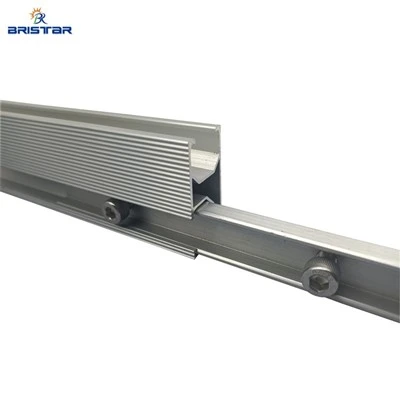
A properly specified solar mounting rail connector should maintain rail alignment, provide sufficient load transfer, avoid excessive restraint of thermal expansion, and preserve the required electrical bonding path where the racking system is used as part of the equipment grounding arrangement.
Long-Span Solar Rail Joints and Stress Concentration
Long solar rail runs are exposed to repeated temperature changes, wind pressure, snow loading and installation tolerances. Aluminum rails have a relatively high coefficient of thermal expansion, so a long continuous rail can experience measurable dimensional movement between hot and cold operating conditions.
At a splice, several forces may interact:
- Bending moment from module and wind loads
- Shear force transferred between adjacent rail sections
- Local bearing stress around connector fasteners
- Thermal expansion and contraction
- Rail rotation caused by uneven support conditions
- Differential movement between roof attachments and rails
The splice should therefore be positioned according to the structural calculation rather than simply installed at the most convenient rail location.
For long-span solar racking, the engineering review should establish the following parameters:
| Design Parameter | Engineering Consideration |
|---|---|
| Rail profile | Section geometry, wall thickness and moment of inertia |
| Rail material | Commonly AL6005-T5 aluminum |
| Rail span | Distance between roof or ground supports |
| Splice position | Determined from bending and support conditions |
| Wind load | Project-specific; AS/NZS 1170.2 may apply |
| Snow load | Project-specific site calculation |
| Fasteners | SUS304 or specified structural fastener grade |
| Connector engagement | Defined by rail profile and connector geometry |
| Thermal movement | Calculated from rail length and temperature range |
| Grounding path | Verified according to the complete racking design |
A splice that is structurally adequate for a short rail section may not provide the same performance when used repeatedly across a long rail array. Connector length, fastener arrangement and rail engagement should therefore be reviewed together with the rail cross-section.


Internal Solar Rail Splice Connectors and Expansion Joint Design
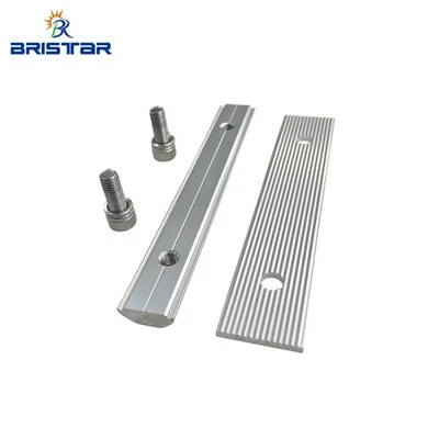
An internal solar rail splice connector is typically inserted into the hollow section of two adjacent rails. The connector provides controlled mechanical engagement while keeping the external rail surface available for PV module clamps.
The connector geometry should match the internal rail cavity. Excessive clearance can permit rail movement and joint rotation, while insufficient clearance can complicate installation and restrict thermal movement.
For long rail assemblies, three dimensions require particular attention:
1.Insertion length - sufficient engagement is required on both rail sections.
2.Fastener location - fasteners must not interfere with rail expansion or create excessive local stress.
3.Joint gap - the gap should follow the system's calculated thermal movement requirement.
Thermal Expansion in Aluminum Solar Rails
The approximate thermal expansion of an aluminum rail can be calculated using:
ΔL = α × L × ΔT
Where:
- ΔL = change in rail length
- α = coefficient of thermal expansion
- L = original rail length
- ΔT = temperature variation
For aluminum, a commonly used engineering value for preliminary calculation is approximately 23 × 10⁻⁶ /°C. The final value and design temperature range should follow the specified aluminum alloy data and project design conditions.
For example, a 20 m aluminum rail exposed to a 60°C temperature difference could experience approximately:
23 × 10⁻⁶ × 20 × 60 ≈ 27.6 mm
Hook: Verify your long-span rail joint before repeated field installation.
Request a Solar Rail Splice Engineering Review
Strength and Load Transfer at Solar Mounting Rail Connectors
A solar mounting rail connector must transfer the forces generated at the rail junction without causing excessive local deformation.
The most important structural checks normally include:
1.Bending Load Transfer
The rail carries loads from PV modules into roof attachments, ground supports or other mounting points. The splice must maintain sufficient resistance against local bending and rail rotation.
2.Shear Transfer
Wind uplift and downward pressure can generate shear forces along the rail. Connector engagement and fastener capacity should be checked against the calculated design shear.
3.Local Bearing Stress
The connector and fasteners introduce concentrated forces into the aluminum rail. Excessive bearing stress can deform the rail wall around the fastener hole and reduce joint stiffness.
4.ull-Out and Fastener Capacity
Fastener capacity must be assessed according to the selected fastener material, diameter, thread configuration and rail geometry. SUS304 fasteners are commonly used for corrosion-resistant solar mounting hardware, but the structural calculation should verify the required capacity for the project.
5.Rail Deflection
The splice should not be evaluated independently from the complete rail system. Rail span, support spacing, module loading and wind pressure all affect the resulting deflection.
For projects designed under AS/NZS 1170.2, the wind actions should be established from the project location and building or array characteristics rather than assigning one generic wind value to every installation.
Conclusion: Designing a Continuous Solar Rail Junction
A continuous solar rail junction is a structural and installation-control point within a long-span PV mounting system. The splice must provide adequate mechanical load transfer while allowing the calculated thermal movement of the aluminum rail assembly.
For procurement teams, the key checks are not limited to connector price or nominal rail compatibility. Rail profile matching, connector engagement, fastener specification, expansion allowance, corrosion environment and grounding continuity should all be confirmed before bulk production.
FAQ: Solar Rail Splice Engineering and Procurement
How should a solar rail splice kit be positioned on a long PV rail?
The splice position should follow the structural calculation, support spacing and rail bending profile. Avoid placing joints solely for manufacturing convenience. The design should also account for thermal expansion and the required rail movement allowance.
Can a solar mounting rail connector also provide grounding continuity?
Not automatically. Mechanical connection does not guarantee electrical bonding, particularly with anodized aluminum surfaces. If the rail forms part of the grounding system, electrical continuity should be verified using the specified bonding component or grounding method.
What information is required for bulk solar rail splice production?
Provide the rail extrusion drawing, internal cavity dimensions, rail length, support spacing, fastener specification, project wind and snow loads, temperature range, grounding method and required quantities. These inputs allow connector dimensions and joint configuration to be matched before production.