

Equipotential bonding across photovoltaic (PV) array structures requires breaking the non-conductive oxide layer on anodized AL6005-T5 aluminum rails and module frames to establish a continuous low-resistance electrical path (< 0.1 Ω). Grounding clips with stainless steel SUS304 teeth, bonding jumpers, and tin-plated copper ground lugs prevent static charge accumulation and safely divert fault currents up to 10 kA to the grounding electrode system per NEC 690.43 and UL 2703 standards.
Technical Mechanics of PV Array Fault Current Pathways
Solar mounting structures operate in exposed outdoor environments subject to atmospheric surges, insulation failures, and induced lightning currents. Anodized aluminum profiles feature a non-conductive surface oxide layer with a thickness ranging from 10 μm to 25 μm. Without mechanical penetration of this layer, individual structural members remain electrically isolated, creating high-impedance boundaries that present severe shock hazards and arc fault risks.
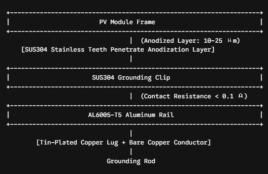
Establishing equipotential bonding across the racking system requires accessories certified under UL 467 (Grounding and Bonding Equipment) and UL 2703 (Mounting Systems, Mounting Devices, Clamping/Retention Devices, and Grounding Lugs for Use with Flat-Plate Photovoltaic Modules and Panels). Contact resistance across bonded joints must be maintained below 0.1 Ω throughout a 25-year operational lifecycle under thermal cycling (-40°C to +90°C) and corrosive ambient conditions.
Grounding Accessories: Material Specifications & Mechanical Mechanics
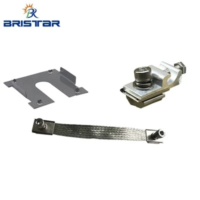

| Component Name | Material Standard | Penetration Mechanism | Primary Function |
| Solar Grounding Clip | SUS304 Stainless Steel (Hardened) | Multi-point sharp nibs penetrate 10–25 μm anodization layer | Bonds PV module frame directly to mounting rail via clamp pressure |
| Solar Bonding Jumper | Tin-Plated Braided Copper Wire (10 AWG / 6 mm²) | Bolt-on terminal lugs with serrated lock washers | Bridges isolated structural sections across rail splices or expansion joints |
| Solar Racking Grounding Lug | Tin-Plated Copper / Forged AL6005-T5 with SUS304 Hardware | Direct wire-clamping bolt accepting 4–14 AWG bare copper conductor | Connects rail circuit to main equipment grounding conductor (EGC) |
Solar Grounding Clip
Positioned between the PV module frame and the AL6005-T5 aluminum mounting rail under Solar Panel Clamps, the stainless steel grounding clip uses stamped teeth. When technicians tighten the clamp fastener to the specified torque rating (14–18 N·m), these teeth pierce both the module frame's anodized layer and the rail finish. This creates a gas-tight, low-impedance metallic contact point that withstands thermal expansion and mechanical vibration without gas-void oxidation.
Solar Bonding Jumper
Rail splices interrupt the continuous conductive pathway of racking lines. Flexible braided copper jumpers terminated with tin-plated ring lugs span across structural joints. The tin coating prevents galvanic corrosion when in contact with aluminum rail surfaces. The high-flexure braid accommodates structural deflection driven by wind loading (tested up to 60 m/s according to AS/NZS 1170.2 specifications) and thermal movement without work-hardening or fatigue failure.
Solar Racking Grounding Lug
The grounding lug serves as the terminal interface between the aluminum racking system and the copper equipment grounding conductor (EGC). Utilizing tin-plated copper or specialized aluminum alloy bodies paired with SUS304 fasteners, the lug grips 4 AWG to 14 AWG solid or stranded copper wire. Serrated bottom surface patterns bite through the rail anodization during bolt installation, eliminating the requirement for manual surface scraping during field installation.
√:Evaluate customized high-durability grounding accessories designed for large-scale utility and commercial mounting systems.
Contact Our Engineering Team for Custom OEM Hardware
Corrosion Prevention & Mechanical Compliance Standards
Galvanic corrosion occurs when dissimilar metals meet in the presence of an electrolyte (such as rainwater or salt spray). On the anodic index, the potential difference between unpassivated aluminum (-0.90 V) and copper (-0.22 V) exceeds the acceptable 0.15 V threshold for high-humidity outdoor applications.
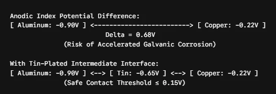

To mitigate accelerated degradation:
1.Tin Plating Interface: Ground lugs and copper components undergo 8–12 μm electro-tin plating to serve as a buffer layer between copper and AL6005-T5 aluminum.
2.SUS304 Stainless Steel Hardness: Stainless clips undergo mechanical hardening (tensile strength ≥ 750 MPa, yield strength ≥ 240 MPa) to maintain penetration force against the hard aluminum oxide outer skin (Vickers hardness HV 200–500).
3.EPDM Gasket Integration: Flashing plate assemblies incorporate UV-stabilized EPDM rubber gaskets (70 Shore A hardness) to isolate mechanical fasteners from moisture intrusion at roof penetration points.
International Testing & Standard Compliance
1.UL 467 & UL 2703: Continuous current pull testing, short-circuit current stress tests, and grounding continuity testing.
2.IEC 61730-2: Safety qualification testing for PV modules, including ground continuity and bonding path integrity.
3.ISO 9227 Salt Spray Test: Minimum 1,000-hour neutral salt spray (NSS) test performance for marine and coastal installations.
4.AS/NZS 1170.2: Wind action structural compliance for mechanical rigidity under extreme dynamic load conditions up to 1.4 kN/m² snow load and 60 m/s wind speed.
FAQ
Q: How do solar grounding clips eliminate manual wire scraping during installation?
A: Grounding clips feature hardened SUS304 stainless steel nibs that pierce through the 10–25 μm non-conductive anodized layer of aluminum frames and rails when tightened to the design torque (14–18 N·m). This establishes a gas-tight electrical bond automatically, eliminating manual oxide layer scraping.
Q: What specifications prevent galvanic corrosion between copper grounding wire and aluminum rails?
A: Direct contact between copper wire and aluminum creates high galvanic potential differences (> 0.15 V). Tin-plated copper lugs or aluminum-bodied ground lugs with tin interfaces isolate the metals, preventing galvanic oxidation and maintaining low circuit resistance (< 0.1 Ω) in outdoor environments.
Q: What are the minimum order requirements and custom production lead times for wholesale OEM accessories?
A: Standard MOQ for wholesale customized grounding clips, bonding jumpers, and grounding lugs starts at 10,000 units per item. Standard factory production lead time is 15 to 21 days post-drawing approval, with full OEM dimensional custom options, custom packaging, and UL material certification reports included.